 |
| • | AppendConsumeBuffers: | Example for using append and consume buffers (GPU). |
| • | AreaLights: | An area light (rectangular shaped) illuminating a normal-mapped surface. |
| • | BlendedTerrain: | An application to illustrate multitexturing of a terrain and sky. |
| • | BufferUpdating: | A simple example to illustrate how to update buffers between CPU and GPU. |
| • | BumpMaps: | Bump mapping of a torus. |
| • | CubeMaps: | Cube-based environment mapping. |
| • | GeometryShaders: | Billboards using geometry shaders; example of SV_VERTEXID semantic. |
| • | GlossMaps: | Gloss maps that use the alpha channel for illumination. |
| • | IEEEFloatingPoint: | Simple example to show GPU handling of subnormal floating-point numbers. |
| • | Lights: | Standard lighting (point, directional, spot). |
| • | LightTexture: | Point or directional lighting with materials and textures. |
| • | MultipleRenderTargets: | Use of multiple render targets in pixel shader. Various HLSL features are also illustrated. |
| • | PlanarReflections: | A simple example for drawing the reflection of two objects on two planes. |
| • | PlanarShadows: | A simple example for drawing the shadow of two objects on two planes. |
| • | PlaneMeshIntersection: | Rendering of the intersection of a mesh with two families of parallel planes. |
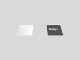
| • | ProjectedTextures: | A simple example for projecting a texture onto geometry. |
| • | ShaderReflection: | A tool for exploring the HLSL shader reflection. |
| • | ShadowMaps: | An example of shadows using a computed shadow texture. |
| • | Skinning: | A simple illustration for shader-based skinning. |
| • | SphereMaps: | Sphere-based environment mapping. |
| • | StructuredBuffers: | Use a structured buffer as an unordered access view (UAV) in a pixel shader. |
| • | TextureArrays: | How to use a texture-array resource (not an array of texture resources). |
| • | TextureUpdating: | A simple example to illustrate how to update textures between CPU and GPU. |
| • | Texturing: | Simple 2D texturing; uses the built-in Texture2DEffect class. |
| • | VertexColoring: | Simple vertex coloring; uses the built-in VertexColorEffect class. |
| • | VertexTextures: | A simple example of displacement mapping using vertex textures. |
| • | VolumeFog: | Volumetric fog using simple shaders and CPU-based geometric slab manipulation. |
| • | WireMesh: | Draw the edges of a triangle mesh in a color different from the mesh. |
| AppendConsumeBuffers. A simple illustration of how to use append-consume buffers. The shader has an input append buffer and returns a consume buffer that contains every other input. |
AreaLights. An area light (rectangular shaped) illuminating a normal-mapped surface.
An orientation of the surface to show the area lighting and the normal mapping.
|
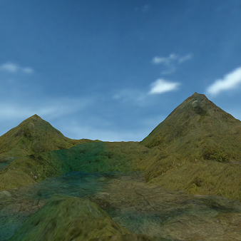
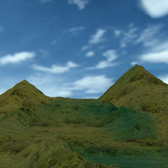
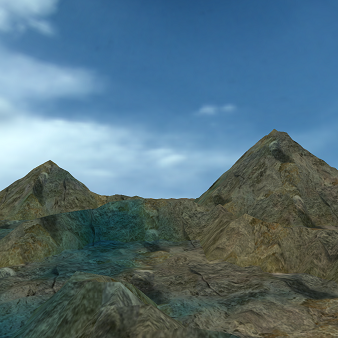
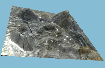
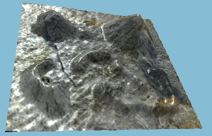
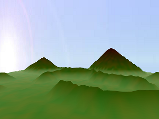
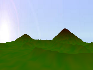
BlendedTerrain. A terrain is constructed as a height field from a gray-scale image. It is
textured using a blend of stone and grass 2D textures. The blending is
controlled by a 1D texture used as a table of weights. An animated sky
dome rotates about the up vector. Shadows of the clouds are simulated and
drawn as another texture layer on the terrain. The shadows move across
the terrain.
The left image is a screen capture on start up. You can see the cloud shadows
on the terrain. The blending can be biased towards grass or stone using a
pixel shader constant. The middle image is biased towards grass. The right
image is biased towards stone.
|
| BufferUpdating. A simple example to illustrate how to update buffers between CPU and GPU. |
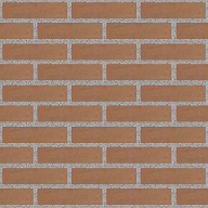
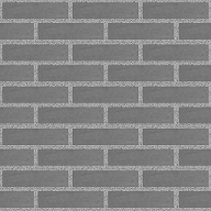
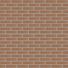
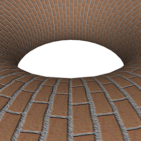
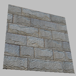
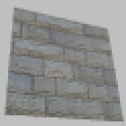
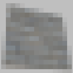
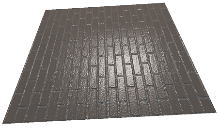
BumpMaps. Bump mapping of a torus.
The left image is the original brick texture. The middle image is a
gray-scale conversion that is used for normal map generation. The right
image is a normal map for the texture.
|
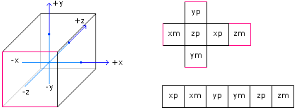
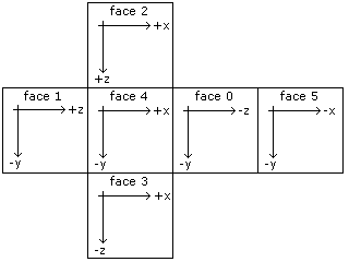
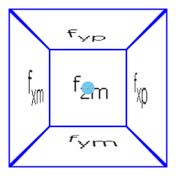
CubeMaps. Cube-based environment mapping.
The coordinate system used by the cube and the face layout are shown in this
image. In the application, the camera has view direction in the -z direction,
up direction is in the +y direction, and right direction in the +x direction.
The face coordinate systems are shown in this image.
The initial display of the application is shown in the left image. The cube faces have textures to identify which faces they are relative to the cube coordinate system. A textured sphere is placed in the center of the cube. The cube faces are reflected by the sphere. The camera is translated backwards out of the cube to obtain the right image. You may wander around the sphere, looking at it from different angles, to see that indeed the cube faces are correctly reflected.
|
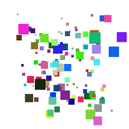
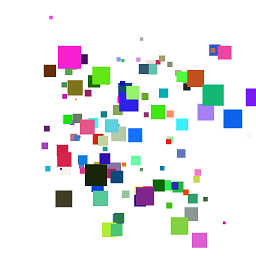
GeometryShaders. Geometry shaders to generate billboards. The sample has two shaders. The first
uses the standard passing of a vertex structure to the vertex shader main program.
The second uses the SV_VERTEXID semantic to pass indices to the vertex shader main
program, and those indices are used to look up values in a structured buffer. This
allows you to produced non-vertex-buffer outputs from, say, compute shaders, and
then attach them as a resource directly to other shaders. It is not possible to
generate a vertex buffer resource as an output, so the index mechanism is important
to avoid downloading output to the CPU, repackaging it as a vertex buffer, and then
uploading it to the GPU.
The billboards are on a virtual trackball. The two images show the billboards
with slightly different trackball orientations.
|
GlossMaps. Gloss maps that use the alpha channel for illumination.
A GlossMapEffect is attached to a square with a texture whose alpha channel
is used to control specular lighting. The three images show different
orientations of the square relative to a fixed light source.
|
| IEEEFloatingPoint. The sample was written to verify the difference in behavior of 32-bit subnormal numbers (flushed to zero) and 64-bit subnormal numbers (not flushed to zero). The sample will be expanded as other verifications are needed about IEEE floating-point in HLSL shaders. |
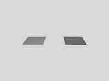
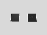
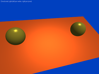
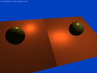
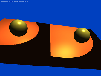
Lights. Typical use of basic lighting effects, including directional lights,
point lights, and spot lights.
The left image has directional lights. The middle image has point lights.
The right image has spot lights. In each image, the left-half is per-vertex
lighting and the right-half is per-pixel lighting.
|
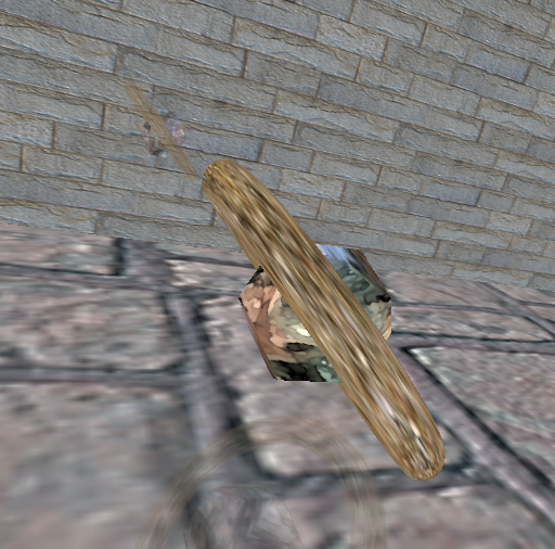
LightTexture. An illustration of combining texturing and per-pixel directional lighting.
The two screen captures show the directional lighting and texturing for two
different orientations of the mesh. Equivalently, the lighting is for two
different light direction vectors.
|
|
MultipleRenderTargets. An example of how to use multiple render targets in a pixel shader. Other
HLSL features are also illustrated.
The row0-column0 image is a rendering of a square with a stone texture using
a draw target consisting of two render targets and one depth-stencil texture. The
pixel shader samples the stone texture and assigns it to render target SV_TARGET0.
The pixel shader has the screen position of the pixel as input via the SV_POSITION
semantic. This position is assigned to render target SV_TARGET1. Rather than output
(implicitly) the perspective depth to the depth buffer, the pixel shader computes
the linearized depth from the perspective depth and assigns it to the depth target
SV_DEPTH. The draw target is enabled, the square drawn, and render target 0 is
attached to an OverlayEffect object which is then drawn to produce the row0-column0
image.
The draw target was specified to generate mipmaps automatically for the render targets. The row0 images in columns 1 through 3 and the row1 image in column0 are obtained from OverlayEffect objects that use mipmap levels 1 through 3 only. The mipmap selection for row0-column0 uses the default algorithm provided by the HLSL function Texture2D.Sample. The next four mentioned use the HLSL function Texture2D.SampleLevel to specify the miplevel to use (and only that miplevel). As expected, each miplevel image appears to be averages from the previous level. The row1-column1 image is obtained from an OverlayEffect object whose pixel shader SV_TARGET0 output is the linearized depth computed by the shader for row0-column0. The OverlayEffect knows only 2D rendering, but it uses the screen position texture computed by the shader for row0-column0 to look up the correct linearized depth value for each pixel. Thus, the output looks as if we actually rendered the square with the (monochrome) linearized depth texture. The pixel shader for row1-column1 also writes a constant color (0.4,0.5,0.6,1.0) to an unordered access view (UAV) using the screen position texture for output location. The row1-column2 OverlayEffect has that UAV attached as an input texture. This is an artificial example that simply shows that you can write to a resource in a pixel shader. The row1-column1 image appears to be solid black. Nearly all the pixels are close to the near plane, so the linearized depth is nearly 0 and the monochrome coloring appears to be black. The row1-column3 image is obtained by moving the camera backwards, away from the square, so that the square's upper-right corner is clipped by the far plane. Now you can see the variation in linearized depth. At that clipped corner, the pixels are nearly at the far plane and their linearized depth is nearly 1. You can see the gray-scale variation near that corner.
|
PlanarReflections. A simple example for drawing the reflection of two objects on two planes.
A dodecahedron and torus are reflected on two planes (floor and wall). For some
reason the OpenGL version draws the wall reflection so that it is more dim than
the DirectX 11 version.
|
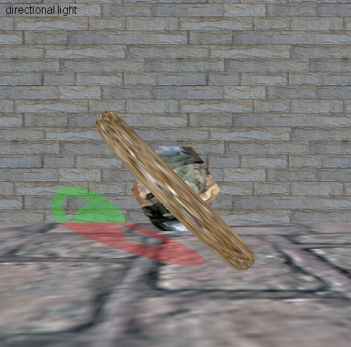
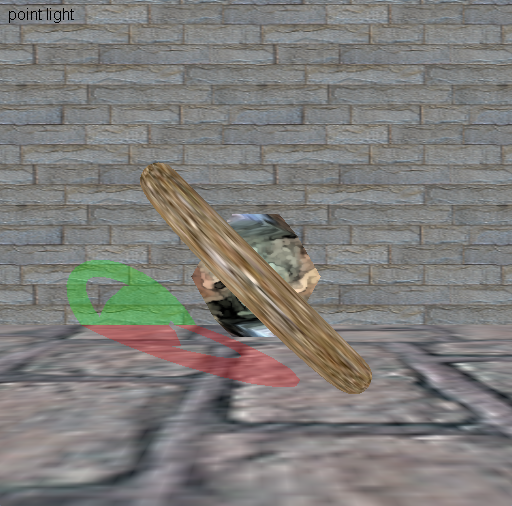
PlanarShadows. A simple example for drawing the shadows of two objects on two planes.
A dodecahedron and torus have shadows drawn on two planes (floor and wall). The floor
shadow color is red and the wall shadow color is green. Both colors have alpha
channels smaller than 1 to allow blending of the shadow with the textures. The left
image shows the shadows using a directional light. The right image shows the shadows
using a point light.
|
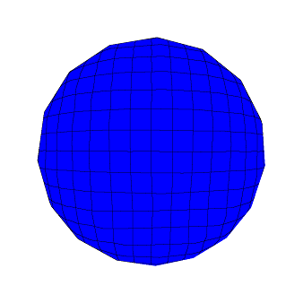
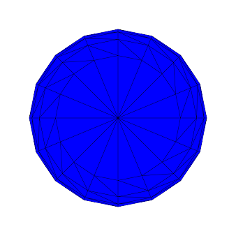
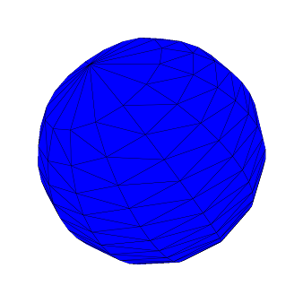
PlaneMeshIntersection. A triangle mesh is intersected by two families of parallel planes. The
intersections of the planes with the mesh are drawn in black and the
other triangle points are drawn in blue. The intersections are not
explicitly calculated; rather, the "wireframe" you see is based on using
a compute shader to determine the color of a pixel based on how close
the corresponding 3D point is to the planes. This is an example of
using screen-space information to help determine output pixel colors, and
no depth-buffer aliasing artifacts occur as they do when you actually try
to draw polylines on top of the surface.
The mesh is a sphere and the families of planes are orthogonal. The
idea works for any type of geometry, not just spheres. The planes are fixed
in space. As you rotate the mesh using the virtual trackball, the intersection
curves are updated.
|
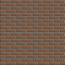
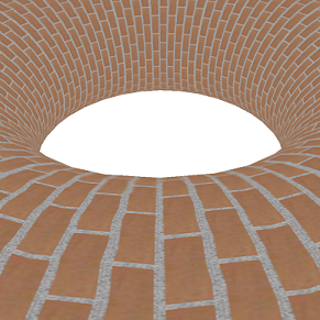
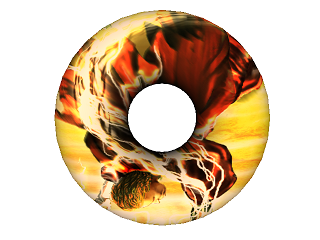
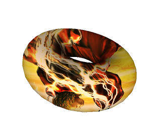
ProjectedTextures. A simple example for projecting a texture onto geometry.
The images show the toroidal mesh in two different orientations, each with the
texture projected from the camera position.
|
| ShaderReflection. This is a tool for exploring the HLSL/GLSL shaders using reflection. You can run this sample on any HLSL/GLSL programs of your choosing. |
ShadowMaps. Basic shadow maps but with postprocessing of the
shadow map by a Gaussian blurring filter to produce soft edges.
The sample is motivated by
Soft-Edged Shadows,
although my shaders are not exactly the same as in this article and the
final pass pixel shader produces a spot-light effect by clamping the
projected texture coordinates to a disk centered in the texture.
This sample illustrates the use of floating-point render targets. The
screen captures are for a couple of orientations of the scene graph
and camera.
|
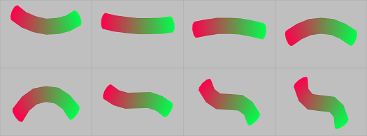
Skinning. A simple illustration for shader-based skinning.
Here are several screen captures from the application. The bones are
randomly generated to cause the object to continuously deform. The
sequence of deformations is from left to right and then from top to
bottom.
|
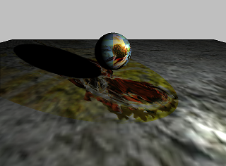
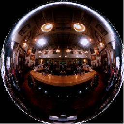
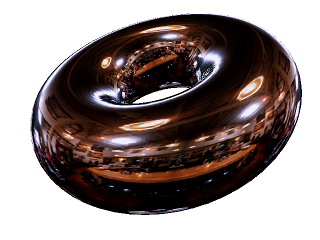
SphereMaps. Sphere-based environment mapping.
The left image is what is to be reflected by the sphere-mapping. The
right image is the rendering of a torus with the reflected image.
|
| StructuredBuffers. An example of a structure buffer as an unordered access view (UAV) written to in a pixel shader. |
| TextureArrays. A simple example to show how to use texture arrays. In a shader program, a texture-array resource of N textures counts as 1 resource (1 binding point). An array of N textures counts as N resources. |
| TextureUpdating. A simple example to illustrate how to update textures between CPU and GPU. |
| Texturing. A simple example to show 2D texturing. The sample uses the built-in Texture2Effect for the shader programs. |
| VertexColoring. A simple example to show vertex coloring. The sample uses the built-in VertexColorEffect for the shader programs. |
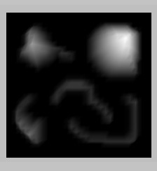
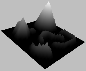
VertexTextures. A simple example of displacement mapping using vertex textures.
The first image shows a top-down view of the object, so what you see is the
gray-scale image used for the displacement map. The second image shows the
object rotated so that you can see the displacement.
|
VolumeFog. Volumetric fog using simple shaders and CPU-based
geometric slab manipulation.
The leftimage shows a rendering of the fog. The geometric slab is a
rectangular solid near the ground level. The density of the fog
at a pixel is proportional to the length of the line segment of
intersection of a camera ray through that pixel and the slab. The
right image shows a rendering without volumetric fog.
|
WireMesh. Drawing mesh edges on top of the solidly drawn mesh to emphasize the
edges has visual artifacts due to z-buffer fighting. An alternative
uses screen-space information to determine whether to draw a pixel
as an interior triangle point, an edge point, or a mixture of both
when the point is near an edge. This example shows how to tell the
rasterizer to use affine interpolation rather than perspective
interpolation of vertex attributes.
Two different orientations of the mesh.
|